If you have ever competed in VEX you know how painful programming the cortex is.
In order to develop your robot code you have to plug into the robot or controller, upload, wait several seconds, reset the field, test your code, and repeat. Sometimes you may not even have physical access to a robot which makes the entire process even slower.
So far has been only one way to simulate your robot which is RVW (Robot Virtual Worlds). Unfortunately RVW only works for RobotC code and you only have a handful of pre-built virtual robots to choose from making it useless for most teams.
What compounds issues even more is that the Cortex does not have any officially supported debugging functionality, we do not have a JTAG port to attach a debugger when things go wrong.
I aimed to solve this issue by implementing a way of simulating your robot hardware seamlessly but there a few technical challenges to overcome before that is possible, to explain these challenges first lets look at a block diagram of the cortex:
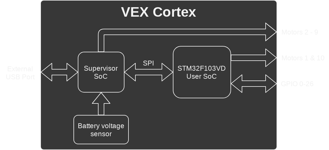
Ideally we do full emulation including both the supervisor and user SoCs so that we can execute the exact binaries that are used on a real robot, I quickly realized how difficult that would be as the supervisor's pinout is not documented and the protocol it uses to communicate with VEXNet keys is not documented.
The user SoC is a STM32F103VD with 384K flash, 64k ram, and a Cortex-M3 armv7-m processor. QEMU itself supports Cortex-M3 but only a very limited number of SoCs and development boards not including anything stm32.
Support for stm32 specifically is extremely important because timers, interrupt control, dma, and most other mmio functionality is vendor specific.
Turns out there is a qemu fork that adds stm32 support for the stm32f103xx SoCs here.
This fork includes enough to get PROS running out of the box and even print messages to UART without any modifications to the kernel.
This is great but unfortunately I2C and SPI aren't implemented and the ADC is incomplete (lacks continuous conversion mode). I need SPI for the supervisor or user code won't even run, I2C is needed to simulate IMEs, and the ADC is needed to simulate analog sensors.
To work around these issues instead of rewriting everything I opted to modify the pros kernel to do all I/O through custom hardware.
First step was to make a custom qemu device for the vex cortex implemented here.
Pretty straight forward, just a stripped down version of the stm32f103c8 device.
Next I needed to write qemu hardware here to communicate with the kernel, to do this i needed the following:
- A timer to update supervisor every couple ms
- The irq list for the cortex so I can poke them from qemu
- A memory region that I can control read and writes from on the qemu side
Sadly the qemu internals aren't too well documented so I had to take reference from some other hardware implementaitons (dma, adc, etc.)
Timers are simple:
s->circular_timer = timer_new_ns(QEMU_CLOCK_VIRTUAL, (QEMUTimerCB *)vex_mgr_stream_circular_timer, s)
This creates a nanosecond timer with vex_mgr_stream_circular_timer as a callback when it gets triggered.
uint64_t curr_time = qemu_clock_get_ns(QEMU_CLOCK_VIRTUAL);
timer_mod(s->circular_timer, curr_time + 10000000);
This schedules the timer 10ms in the future
Next we need the irq list, which is returned by stm32_init and can just be passed to vex_mgr_create in vex_cortex_init
Once you have the list (named pic) you can just trigger them with qemu_irq_pulse. The stm32 header conveniently provides definitions for irqs so the following example triggers the SPI1 interrupt as the SPI controller would do when there is data in the SPI buffer sent from the supervisor:
qemu_irq_pulse(s->pic[STM32_SPI1_IRQ]);
Finally the memory region, I picked some reserved space in the stm32 memory map that's at 0x40021400 and 0xC00 (3072) bytes wide. The following code maps it to functions that handle reading and writing:
static const MemoryRegionOps vex_mgr_ops = {
	.read = vex_mgr_read,
	.write = vex_mgr_write,
	.endianness = DEVICE_NATIVE_ENDIAN,
	.impl = {
		.min_access_size = 1,
		.max_access_size = 4,
	}
};

sysbus_mmio_map(SYS_BUS_DEVICE(dev), 0, 0x40021400);
// s->iomem is a MemoryRegion struct
memory_region_init_io(&s->iomem, OBJECT(s), &vex_mgr_ops, s, "vex_mgr", 0xC00);
sysbus_init_mmio(dev, &s->iomem);
Now if the cortex ever tries to read or write from that memory region qemu will immediately call the handlers allowing two way communication.
As with most MMIO on the cortex, in the kernel you define the device as a convenient struct with volatile fields:
typedef struct {
  // Control register
  __IO uint32_t CR;
  // Args
  __IO uint32_t A1;
  __IO uint32_t A2;
  __IO uint32_t A3;
  // Results
  __IO uint32_t R1;
  __IO uint32_t R2;
  __IO uint32_t R3;
  __IO uint32_t R4;
} EMULATOR_TypeDef;

#define EMULATOR ((EMULATOR_TypeDef*)0x40021400)
With the struct and EMULATOR macro we can access the hardware registers by name instead of directly reading and writing from memory.
The emuCall helper function i wrote loads arguments and signals the control register to call a specific function on the qemu side provided a 16 bit module ID and 16 bit function ID. It is this this way instead of passing a function name as a string i.e. "Motor_set" for simplicity as there are only a few dozen functions.
inline int emuCall(uint16_t mod, uint16_t func, uint32_t a1, uint32_t a2, uint32_t a3) {
  _enterCritical();
  EMULATOR->A1 = a1;
  EMULATOR->A2 = a2;
  EMULATOR->A3 = a3;
  EMULATOR->CR = func | (mod << 16);
  int out = EMULATOR->R1;
  _exitCritical();
  return out;
}
The enter and exit critical ensure interrupts are disabled while registers are being accessed, as an interrupt inbetween any of these reads and writes will most likely clobber the argument and return registers.
After that I refactored a good chunk of the kernel to do all I/O through emuCall, you can see the huge commit here.
Here are all the functions that needed to be implemented to remove dependency on standard cortex gpio:
int EmuSerial_init(int port, int baud, int flags);
int EmuSerial_shutdown(int port);
int EmuSerial_putc(int port, int c);

int EmuFS_programOn();
int EmuFS_programOff();
int EmuFS_erasePage(int page);

int EmuI2C_startRead(int addr, void* data, int count);
int EmuI2C_startWrite(int addr, void* data, int count);
int EmuI2C_setAddr(int addr);

int EmuGPIO_ADCInit(uint32_t data);
int EmuGPIO_setDir(int port, int mode);
int EmuGPIO_getInput(int port);
int EmuGPIO_getOutput(int port);
int EmuGPIO_setOutput(int port, int value);
int EmuGPIO_setInterrupt(int port, int edges);

int EmuMotor_get(int channel);
int EmuMotor_set(int channel, int value);
int EmuMotor_stop();

int EmuComp_init();
int EmuComp_enableStandalone();
int EmuComp_setName(char* name);
int EmuComp_getStatus(void* buff);

int EmuSystem_exit();
int EmuSystem_break();
Header where these are defined
On the qemu side most of this will remain stubbed until I have an actual robot simulation to send and recieve all the data from.
For now only UART and the supervisor is fully implemented but that's enough to get the PROS kernel and user code fully running in an emulator:
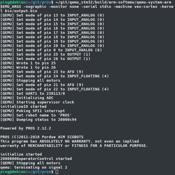
And that's what I have so far! In the future I plan on hooking this up to an Unreal Engine powered robot simulation, tune in for more updates.
