I've made a zachtronics inspired digital circuit simulator in AngularDart.
It was inspired by is one of my favorite zachtronics games, KOHCTPYKTOP. It is a game where you design digital circuits on a grid, closely resembling the CMOS process which is how ICs are made in real life.
If you haven't played it already I highly recommend checking it out: http://www.zachtronics.com/kohctpyktop-engineer-of-the-people/
My recreation features a configurable PCB size, panning, live simulation, and more!
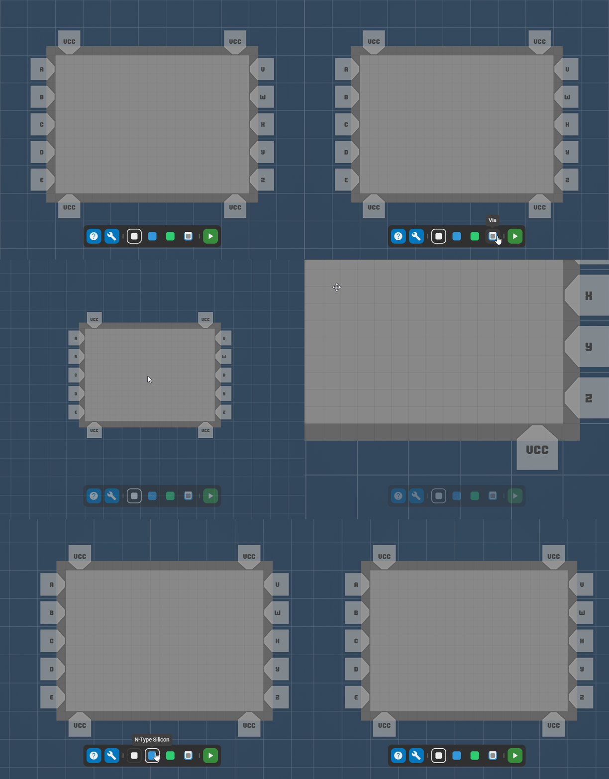
At the bottom there is a toolbox containing the 4 primary elements:
- Metal
- N-Type silicon
- P-Type silicon
- Via
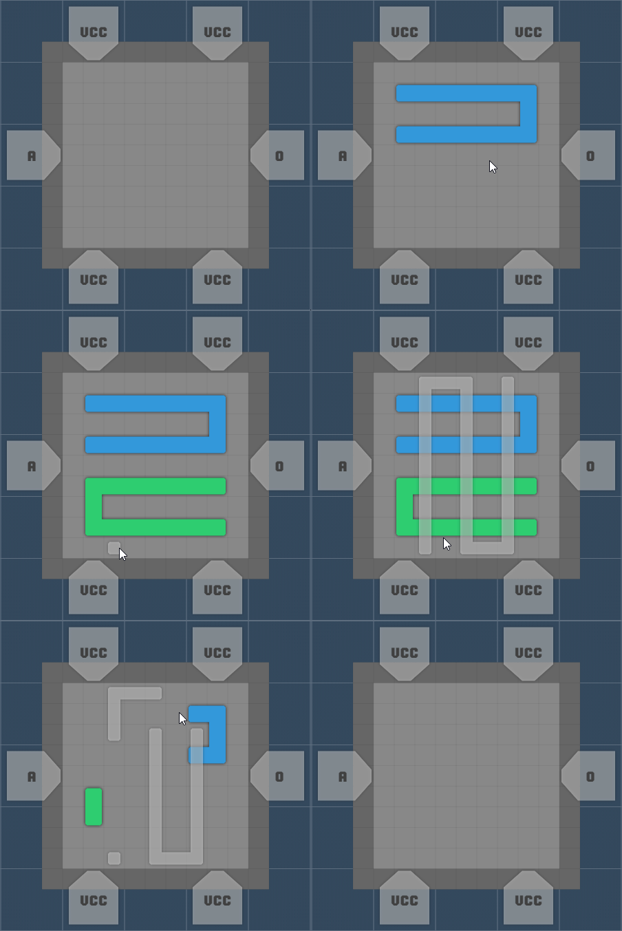
These elements can be placed by click-dragging to form traces:
Metal and silicon conduct electricity provided by inputs to your IC, and the two layers can be connected with a via:
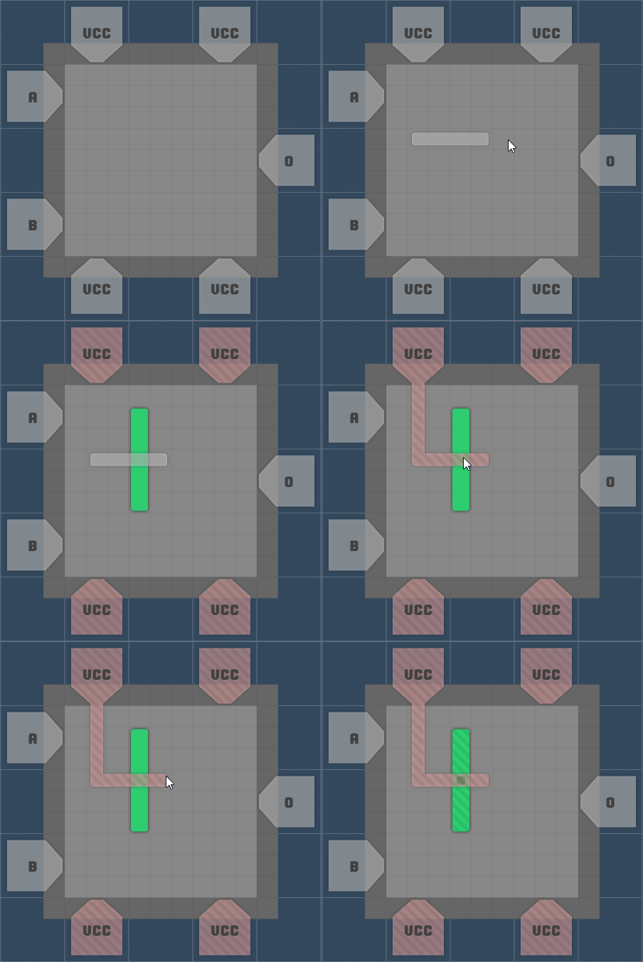
Metal is placed on a layer above Silicon where it conducts electricity separately, the two types of silicon can't be overlapped but can however be used to create gates.
Gates can be created by placing different typed silicon over one another, here is a simple circuit acting as an AND gate:
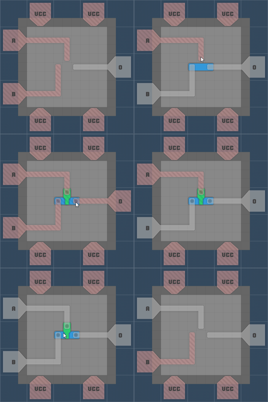
You may have noticed a little blip on the output when A turned off at the same time B turned on, this was because it takes time for gates to activate and deactivate:
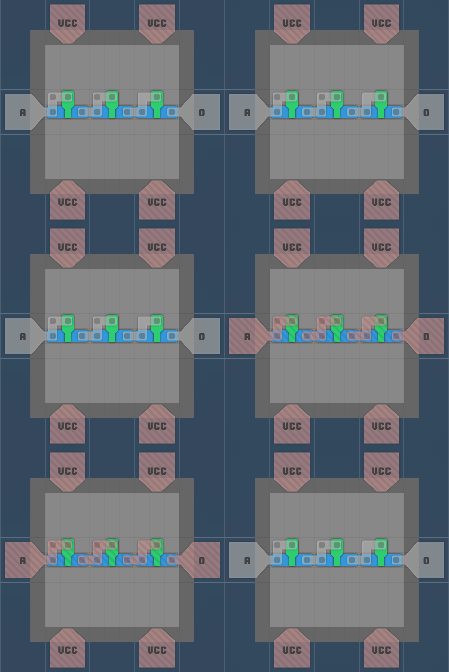
Here it takes time for each gate to turn but the output turns off as soon as the input does because gates are just bridges, the delay is only in it's activation and not the electricity that flows through.
To get a proper delay you would do this:
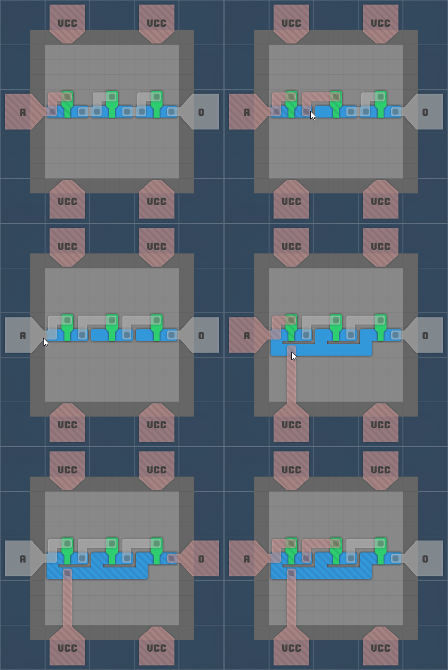
Cool! What about an OR gate:
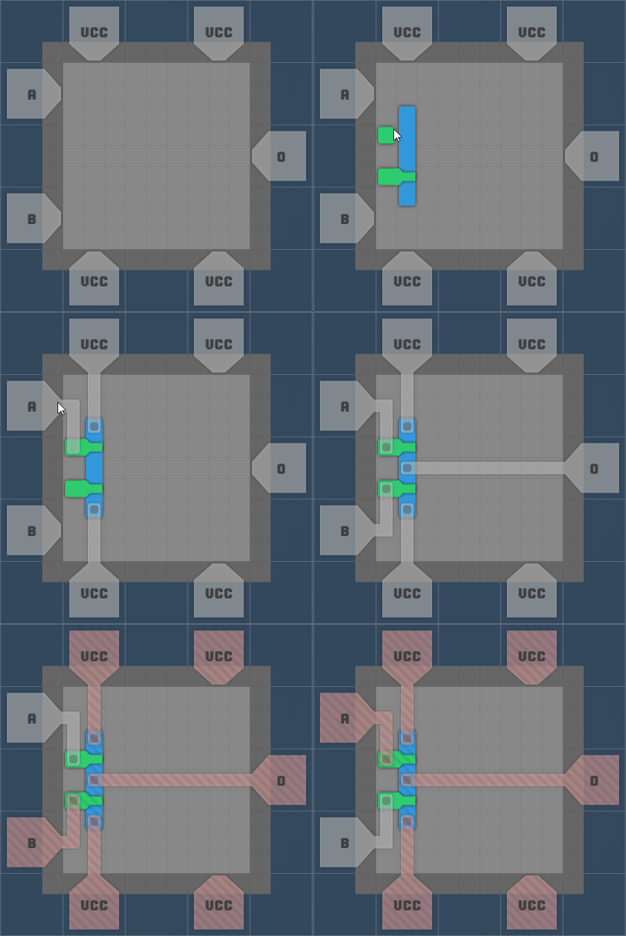
Since there are no diodes the simplest way to make an OR gate is to AND both inputs with VCC and then combine the result.
If PNP transistors are used instead of NPN what you get is a simple NAND gate:
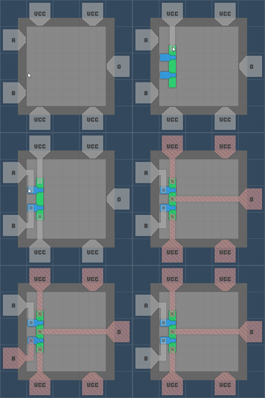
XOR gates are a bit more complicated, here is a version that uses 1 PNP and 3 NPN transistors:
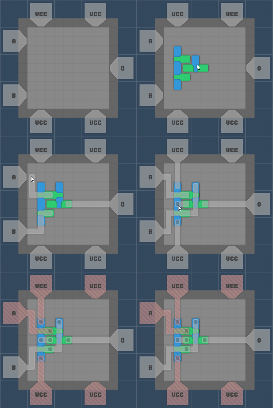
Now for something more interesting, a 2 bit full adder:
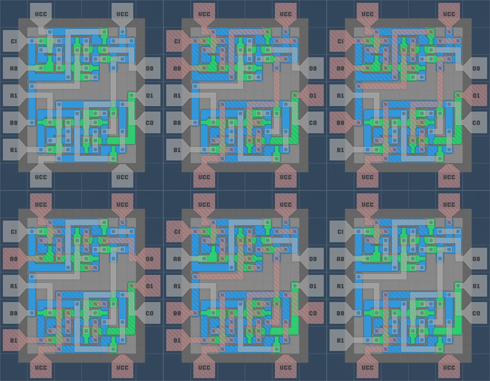
There is a test build up at https://c.tst.sh/ let me know what you think ❤️
